Project 03
Formula Student Pedal Box Design and Optimization
Designed and optimized a competition-compliant, brake and accelerator sensor systems integrated pedal box in SolidWorks for Phoenix Racing's Formula Student race car, weighing 2.5 kg (excluding hardware) while achieving a Factor of Safety ≥1.4 through topology optimization and FEA analysis in ANSYS Mechanical.
- Role
- 3rd Year Individual Project Thesis
- Place of Work

The problem
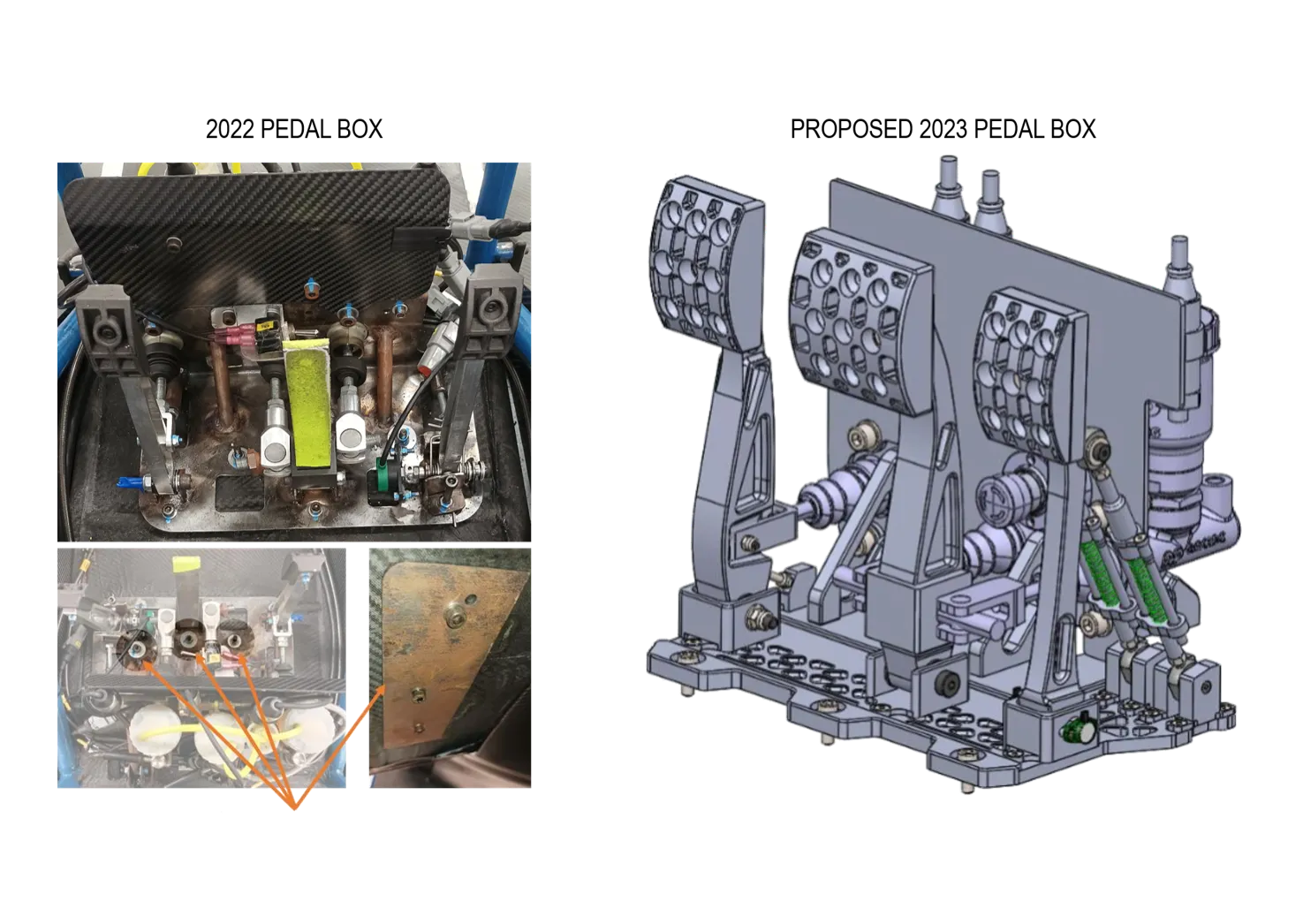
Phoenix Racing’s 2022 pedal box failed to meet IMechE Formula Student regulations (clause T6.1.8) due to 2 mm hot-rolled 4130 steel base sheet”s plastic deformation caused by the applied 2 kN scrutineering load. Supplementary, Brake Over Travel Switch (BOTS) and Accelerator Pedal Position Sensor (APPS) integration was identified as inadequate, requiring enhancements.
Design requirements
2023 Pedal box design proposal constraints and criteria were based on:
| T3.20.1 — All non-crushable objects (e.g. pedals, master cylinders, hydraulic reservoirs) must be rearward of the rear most plane of the front bulkhead and at least 25mm behind the AIP at any time, except for sensors, aerodynamic devices and their mountings. |
|---|
| T4.2.1 — The cockpit must provide a free internal cross section sufficient for the template shown on the right in Figure 12 to pass from the cockpit opening to a point 100mm rearwards of the face of the rearmost pedal in an inoperative position. The template may be moved up and down. Adjustable pedals must be in their most forward position. |
| T4.3.4 — The figure has to be positioned in the vehicle as follows, see Figure 14: The seat adjusted to the rearmost position, the pedals adjusted to the front-most position, the bottom 200mm circle placed on the seat bottom (the distance between the centre of the circle and the rearmost actuation face of the pedals must be minimum 915mm), the middle circle positioned on the seat back, the upper 300mm circle positioned 25mm away from the head restraint. |
| T6.1.1 — The vehicle must be equipped with a hydraulic brake system that acts on all four wheels and is operated by a single control. |
| T6.1.2 — The brake system must have two independent hydraulic circuits such that in the case of a leak or failure at any point in the system, effective braking power is maintained on at least two wheels. Each hydraulic circuit must have its own fluid reserve, either by the use of separate reservoirs or by the use of a dammed reservoir. |
| T6.1.8 — The brake pedal and its mounting must be designed to withstand a force of 2kN without any failure of the brake system or pedal box. This may be tested by pressing the pedal with the maximum force that can be exerted by any official when seated normally. |
| T6.1.9 — The brake pedal must be fabricated from steel or aluminium or machined from steel, aluminium or titanium. |
| T6.1.11 — All brake fluid reservoirs must be shielded from the driver with an impermeable barrier which has a thickness of at least 0.5mm. |
| T6.2.1 — A brake pedal over-travel switch must be installed on the vehicle as part of the shutdown circuit, as in EV6 or CV4.1. This switch must be installed so that in the event of a failure in at least one of the brake circuits the brake pedal over-travel will result in the shutdown circuit being opened. This must function for all possible brake pedal and brake balance settings without damaging any part of the vehicle. |
| T10.1.2 — All threaded critical fasteners must be at least 4mm metric grade 8.8 (OEM parts 3 mm metric grade 8.8), SAE Grade 5 or equivalent or of that specified in the referencing rule, whichever is larger. |
| T11.8 — Accelerator Pedal Position Sensor. |
| T11.8.1 — T11.8 only applies for electric vehicles, see chapter EV, or internal combustion vehicles using Electronic Throttle Control (ETC), see CV1.6. |
| T11.8.2 — The APPS must be actuated by a foot pedal. |
| T11.8.4 — The foot pedal must return to the 0% position when not actuated. The foot pedal must have a positive stop preventing the mounted sensors from being damaged or overstressed. Two springs must be used to return the foot pedal to the 0% position and each spring must work when the other is disconnected. Springs in the APPS are not accepted as return springs. |
| T11.8.5 — At least two separate sensors must be used as APPSs. Separate is defined as not sharing supply or signal lines. |
Finite Element Analysis
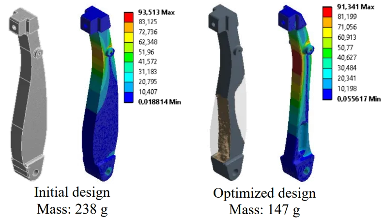
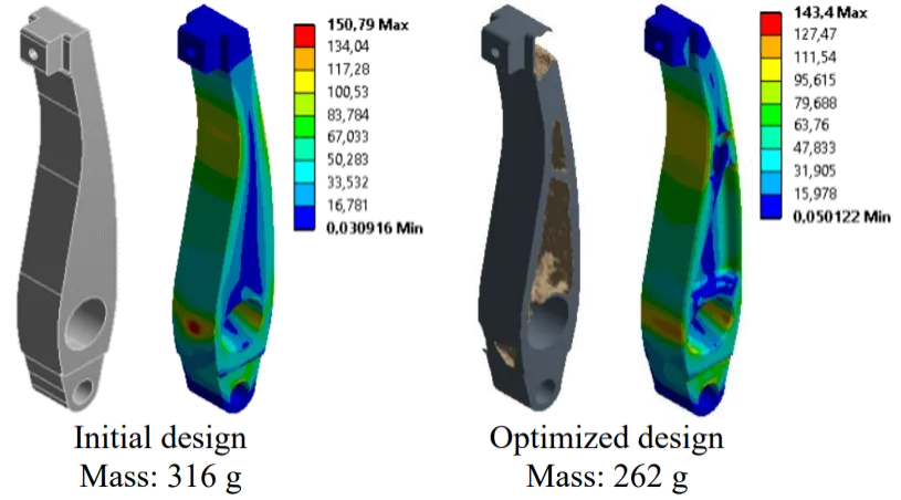
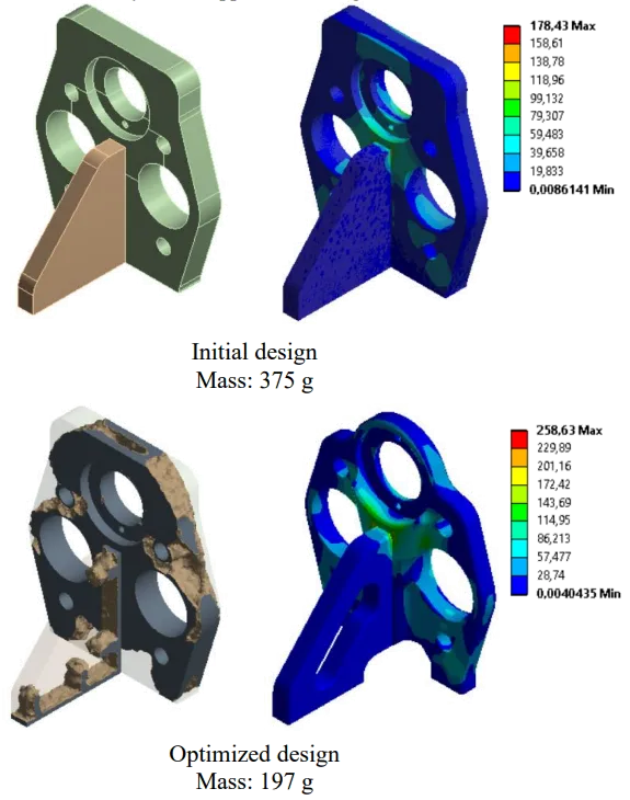
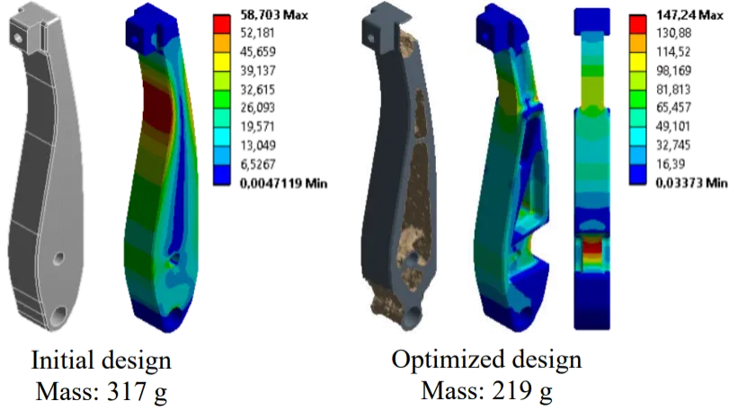
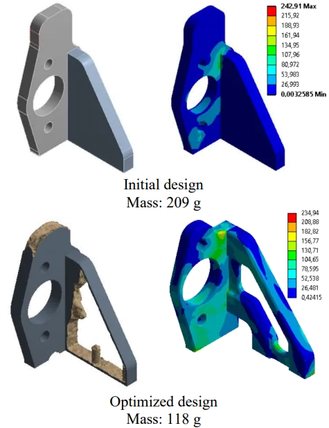
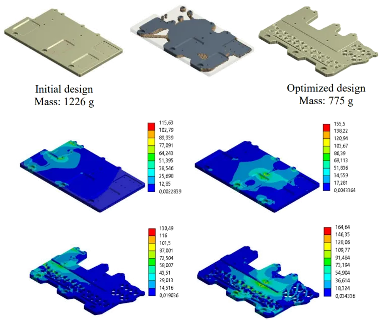
Aluminium 6082-T6 was selected as the feedstock material due to its availability in the in-house machine shop. Thereof, the targeted maximum von-Mises stress was set to 160–170 MPa, accounting for the material’s minimum tensile yield strength of 240 MPa. The results of the finite element analysis (FEA) and topology optimization (TO) study follow below.
1 / 6
Interactive 3D view of Formula Student Pedal Box Design and Optimization